
The word rupture is used to describe breaks or cracks. There are two kinds of breaks: circumferential (guillotine) and longitudinal. There are two types of cracks: through-wall cracks that are postulated (non-mechanistic), and leakage cracks that are based on leak-before-break (LBB) analysis. Ruptures have to be postulated in piping systems, and the effects of these ruptures must be mitigated. Because nuclear power plants are designed, operated, and inspected to prevent such ruptures, these are postulated events, they are sometimes referred to as non-mechanistic to emphasize that they are postulated despite the fact that the piping is designed and inspected to prevent ruptures.
What governs the postulation of pipe ruptures?
Pipe rupture hazards analysis (PRHA) is the set of analyses and qualifications to address 10 CFR Part 50 Appendix A, GDC 4, Environmental and Dynamic Effects Design Bases, which states:
“Structures, systems, or components important to safety shall be designed to accommodate the effects of and to be compatible with the environmental conditions associated with normal operation, maintenance, testing, and postulated accidents, including loss-of-coolant accidents. These structures, systems, or components shall be appropriately protected against dynamic effects, including the effects of missiles, pipe whipping, and discharging fluids, that may result from equipment failures and from events and conditions outside the nuclear power unit. However, dynamic effects associated with postulated pipe ruptures in nuclear power units may be excluded from the design basis when analyses reviewed and approved by the Commission demonstrate that the probability of fluid system piping rupture is extremely low under conditions consistent with the design basis for the piping.”
The idea is to postulate ruptures (breaks and cracks) in pipes, investigate the effects of these breaks on the plant SSCs, and make sure that the plant can be safely shutdown and remain in safe shutdown if one of these ruptures were to occur. The SSCs relied upon to achieve this safe shutdown are called essential.
How is PRHA linked to LBB?
The last sentence of GDC 4, quoted above, the one which starts with “However,” recognizes that a pipe that qualifies for LBB will not suddenly break; it will leak, and the leak will be detected and mitigated before it breaks. For pipes where this LBB behavior can be established, dynamic effects from breaks need not be postulated. But there are three important cautions, regarding LBB:
- First is that LBB does not eliminate the analysis of flooding effects and environmental effects from breaks.
- Second is that LBB does not eliminate the sizing of the emergency core cooling system (ECCS) system for a break.
- Third is that LBB does not eliminate the need to consider the effects of pipe whip and jet impingement on the blowout of insulation and the consequent clogging of the containment sump, which is treated as an ECCS function rather than a dynamic effect. This third effect is addressed in NEI 04-07 and GL 2004-02.
What is meant by PRHA?
The word “rupture” refers to the postulated failures: breaks (circumferential and longitudinal breaks) and cracks (through-wall and LBB-based leakage cracks.)
The “hazards” refer to three types of effects: dynamic effects, environmental effects, and flooding effects. Flooding can be folded under the environmental label.
- Breaks are postulated to occur in high energy (HE) lines (operating temperature in excess of 200 °F or operating pressure in excess of 275 psig) and, in some cases, in moderate energy (ME) lines. Breaks are either circumferential or longitudinal. In turn, circumferential breaks (commonly known as guillotine breaks) are either full separation if the thrust force is sufficient to fully separate the two ends of break (which is commonly the case), or the circumferential break may be of limited separation if the pipe is so rigidly restrained that it cannot move sideways more than its thickness (which is rarely the case). In some of the older plants the definition of HE has an “and” in place of an “or,” so that HE in these older plants are lines operating above 200 °F and 275 psig.
- Through-wall cracks are postulated to occur anywhere around the circumference of HE and moderate-energy lines.
- Leakage cracks are postulated cracks that have a deterministic nature because their location and size are based on an LBB fracture mechanics analysis and on the leak detection capability inside containment.
-Where are the methods and criteria for PRHA spelled out?
The methods and criteria for PRHA are described in SRP Sections 3.6.1 and 3.6.2, and ANS 58.2. While the SRP sections have remained unchanged since the 1970s, some aspects of ANS 58.2, such as the shape of the characteristics of the jet emanating from a break, have evolved in the 2000s, and documented in NEI 04-07 in response to GL 2004-02.
-Where does PRHA fit in the overall design qualification of a nuclear power plant?
PRHA has an important role because it leads to large loads, often the largest loads, larger than seismic loads, on the plant structures. It also can result in a change in plant layout to prevent a whip or jet interaction on an essential target. PRHA will result in the addition of whip restraints and, in some cases, jet shields which are large structures. PRHA also governs the ambient temperatures and pressures for environmental qualification. PRHA must be one of the early layout and design considerations, and not be left for the later stages of design.
-What should be the key elements of an analysis plan for PRHA?
- First, is the delineation of scope boundaries on P&IDs, in particular three types of boundaries: the boundaries of HE lines, the boundaries of break exclusion zones (BEZs) located between containment isolation valves, and the boundaries of the LBB lines.
- Second, within the boundaries of HE lines, the project must define and label each break.
- Third, the thermohydraulic parameters of the line must be established, both at power prior to the break, and after the break as the pipe blows down its contents. This information will be needed to calculate the dynamic, environmental, and flooding effects of the postulated ruptures.
- Fourth is the analysis of the four dynamic effects associated with breaks: (1) pipe whip from thrust forces at the break, (2) jet impingement on nearby targets, (3) blowdown water hammer in the broken line, and (4) mass and energy releases leading to the prediction of subcompartment pressures and temperatures.
- Fifth, the HE and ME breaks and through-wall cracks are compiled and grouped by room or zone, to select those that will lead to the bounding flood levels and environmental effects.
- Sixth, having established the demands caused by the ruptures (dynamic, environmental, and flood), the project determines how these loads affect essential SSCs. Where essential SSCs can be adversely affected, preventive measures must be implemented: moving the essential target, qualifying the target for the load, restraining the broken pipe, or installing jet shields and whip barriers.
What measures are used to counter the effects of pipe ruptures?
The preferred method is to prevent the adverse interaction by relocating the essential targets. Where this is not feasible, then pipe whip restraints (PWRs), bumpers, jet shields, and barriers are used to limit the effects of ruptures. Also, the target can be designed and qualified to operate in the environment caused by the rupture.
What is the zone of influence (ZOI)?
The ZOI of a pipe whip and jet impingement is the arc swept by the whipping pipe, with at its broken end the jet. The ZOI is determined by the location of a hinge point along the broken pipe system, which is determined based on the thrust force and the ruptured pipe’s material dynamic yield strength. Keep in mind that each break causes two ZOIs: one for the pipe upstream and one for the pipe downstream of the break point.
The ZOI can be as large as 180° from the break point, unless an intervening SSC, such as a substantial structure, a wall, or another pipe of equal or larger size and thickness, is impacted in which case the ZOI for pipe whip would be limited by the intervening SSC. Further hinging (a secondary hinge) may form after impact with the intervening SSC. The interaction should also be evaluated to ensure that the whipping pipe is indeed arrested and the strike is not a glancing blow. The ZOI may also be limited by the fluid inventory feeding the break. For example, if the break occurs near a closed valve, and if the valve remains closed after the break, then there will not be enough fluid between the break and the closed valve to cause the whip. This condition is sometimes known as a limited inventory break.
What is the shape of a jet emanating from a break?
There are basically three types of jets to be considered based on the system thermodynamic condition.
- There is the cold water jet (i.e., nonflashing water) with a ZOI that is essentially an axial extension of the pipe diameter, bending down by gravity. There is no axial limit to this jet zone until it reaches a significant intervening structure such as building concrete or steel.
- There is the ANS 58.2 jet. This jet has three regions, with a radially expanding shape. Historically, this ANS jet has been truncated at 10 pipe diameters following NUREG/CR-2913, by Sandia National Laboratories “Two Phase Jet Loads,” 1983. The main steam and MFW lines, for example, would tend to fall under the NUREG jet type.
- There is the more recent (2000s) jet shape that we may call the ACRS jet because it resulted from the questioning of the ANS jet shape by the ACRS. As a result of the ACRS exceptions to the ANS 58.2 conical jet shape, a new spherical equivalent jet was developed and documented in NEI 04-07 to address the blowout of insulation. The spherical shape also accounts for reflections between the incident and nearby SSCs, ignoring shadowing effects.
what are the four basic types of pipe ruptures?
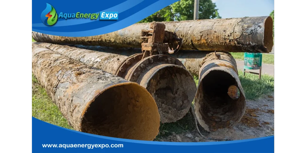
The four basic types of possible ruptures in piping systems include
Brittle fracture
Ductile fracture
Fatigue failure
Creep rupture.
Each rupture type has distinct characteristics and causes, from sudden breakage due to low temperatures (brittle fracture) to slow deformation over time under long-term stress and high temperatures (creep rupture).
How were the PRHA methods and criteria developed?
Early in the design of nuclear power plants, the interest in pipe breaks originated with the need to postulate a break so as to hydraulically size the ECCSs and to determine the highest pressure that can be achieved inside containment. The analysis of breaks then evolved to encompass dynamic effects such as pipe whip and jet impingement, environmental effects, and flooding effects. These new regulatory expectations were spelled out in 1974, in Regulatory Guide 1.46, later replaced by SRP Section 3.6.
The nuclear power industry has studied the dynamic effects of postulated HELB for the past 45 years. These studies have included theoretical (analytical) methods, experimental programs, and numerical research (FEA and CFD analysis). It is worth taking a moment for a brief history of the early developments in this field.
- In 1981–1984, the CEA-CEN (France) conducted tests and studies on the effects of pipe-on-pipe impact using 4-inch whipping pipe on 4- and 2-inch pipe targets. The testing program also included pipe whip impact against steel plates and concrete slabs. The test conditions were those of a PWR at 2400 psi and 600 °F.
- In 1983, Combustion Engineering performed tests on energy-absorbing stainless-steel honeycomb material.
- In 1984–1987, the Pacific Northwest Laboratory conducted for the NRC a series of tests where 6-inch pipes were catapulted against 3–12-inch pipe targets, to investigate the potential for propagation of breaks by pipe-to-pipe impact.
- In 1985 the CEGB and Magnox Electric (UK) conducted pipe whip tests on cantilevered pipe to determine the influence of several factors on the ZOI swept by the whipping pipe. Factors investigated included the direction of the thrust force at the broken end, strain hardening of the pipe material, whipping pipe with multiple bends, and the difference in behavior between opening and closing bends.
- In 1986, in an EPRI-sponsored study, the experimental results for two-phase jets from the Marviken tests were compared to numerical simulations (EPRI NP-4362).
- In 1988 a revised ANS 58.2 was issued, replacing the 1980 edition, introducing several changes as well as the use of the LBB method.
- In 1990, Siemens conducted tests to investigate what happens at the hinge section of a whipping pipe. The hinge section was also tested with a circumferential crack, to investigate the case of a pipe break occurring in a pipe that had a preexisting crack at the buckle section.
- In the mid-1990s the University of Manchester (UK) conducted experimental and numerical studies of the plastic behavior, ovalization of the cross-section, and buckling of whipping pipes as a function of D/t (the ratio of their diameter to their thickness). The flow restriction caused by ovalization is also addressed in the study.
- The 2000s were marked by the study of jet pressure effects on insulation, the concern being the fragmentation of insulation that would find its way into the sump, and possibly block the recirculation flow (GL 2004-02). This question was investigated by the industry through NEI and Owner’s groups, and by the NRC and ACRS, culminating in the spherical jets of NEI 04-07.
Conclusion
In Pipe Rupture Hazards Analysis (PRHA), the human element is crucial for ensuring safety and reliability in nuclear power plants. Effective training and awareness empower personnel to identify and analyze potential rupture scenarios. Clear communication and collaboration among team members foster innovative solutions and comprehensive analyses. A strong safety culture encourages prioritization of safety in daily operations, while feedback mechanisms allow for learning from near-misses and incidents. By emphasizing these human factors, organizations can significantly enhance their PRHA processes and maintain safe operational environments.
To explore the latest innovations in water and energy technologies, and discover a wide range of products and solutions from around the world, you can visit the virtual exhibition AQUA ENERGY EXPO which featuring leading companies in water treatment, desalination, and sustainable energy through the following link: https://aquaenergyexpo.com/
Reference
1.What are the 4 types of pipe ruptures?
https://brainly.com/question/3670082
2.Ruptured Pipe
https://www.sciencedirect.com/topics/engineering/ruptured-pipe
